


Understanding a residential plumbing diagram is one of the most valuable skills any homeowner, DIY enthusiast, or aspiring plumber can develop. Whether you are troubleshooting a persistent leak, planning a bathroom renovation, or simply trying to learn how water flows through your home, a well-drawn plumbing schematic gives you a clear visual roadmap of every pipe, fitting, valve, and fixture in the system.
A residential plumbing diagram is not just a confusing web of lines and symbols — it is the blueprint that reveals how clean water reaches your faucets, showers, and appliances, and how wastewater exits your home safely. In this comprehensive guide, we break down every element of a home plumbing schematic, explain how to read one, compare the different types of diagrams, and answer the most frequently asked questions so you can navigate your home’s plumbing system with confidence.
What a Residential Plumbing Diagram Is and Why It Matters
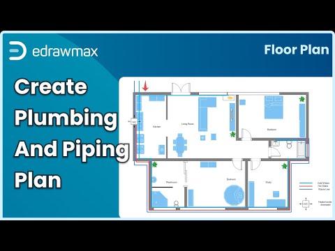
A residential plumbing diagram, sometimes called a home plumbing schematic or plumbing floor plan, is a simplified technical drawing that represents the entire piping network within a house. It maps out the supply lines that bring fresh water in, the drainage lines that carry wastewater away, and the vent stack that regulates air pressure and prevents sewer gases from entering the living space. These diagrams are essential during construction, but they are equally important for renovations, repairs, and inspections.
Without a plumbing schematic, identifying the route of a hidden pipe behind a wall or locating the main shut-off valve becomes a guessing game. A detailed diagram saves time, reduces costly mistakes, and helps professionals communicate more effectively with homeowners and other tradespeople on the job site.
Key Components Shown in a Residential Plumbing Diagram
Every residential plumbing schematic includes several core components that form the backbone of the home’s water system. Understanding what each element represents is the first step toward reading any diagram fluently.
- Water Supply Lines — These pipes transport clean, pressurized water from the municipal main or well pump into the home. Supply lines are divided into hot and cold branches that feed individual fixtures.
- Fixture Connections — Sinks, toilets, bathtubs, showers, washing machines, dishwashers, and water heaters are represented with specific symbols indicating their connection points on the schematic.
- Drain-Waste-Vent (DWV) Pipes — The DWV system handles all wastewater and solid waste removal. Drain pipes carry water downward by gravity, while vent pipes extend upward to the roof to maintain proper atmospheric pressure.
- Shut-Off Valves — Individual fixture valves and the main water shut-off are marked so that emergency water isolation is straightforward during an urgent situation.
- Water Meter and Main Entry Point — The point where water enters the home is clearly indicated, typically near the foundation or utility room.
- Trap and Cleanout Locations — P-traps under sinks and cleanout access points for the sewer line are essential elements that appear on most residential plans.
Supply Side vs. Drain-Waste-Vent (DWV) System
The supply side and the DWV system are the two distinct halves of any home plumbing layout. The supply system operates under pressure and delivers treated water to every outlet. The DWV system relies entirely on gravity and ventilation to move wastewater and sewage downward and outward through larger-diameter pipes into the municipal sewer line or septic tank. A quality residential plumbing schematic will clearly differentiate between these two subsystems using color coding, line styles, or labeled regions.
Reading and Interpreting a Residential Plumbing Schematic
Reading a plumbing schematic may seem intimidating at first, but once you understand the basic conventions, the diagram becomes a practical tool rather than an intimidating technical document. Most schematics use standardized symbols recognized by plumbing codes and architectural standards.
Here are the common symbols and line types you will encounter when studying a plumbing schematic:
- Solid lines represent supply pipes, while dashed lines typically indicate drain pipes.
- Small circles or squares denote fixtures such as faucets, toilets, and drains.
- Thicker lines often indicate larger-diameter pipes like the main stack or sewer lateral.
- Arrow markers show the direction of water flow through the system.
- Crosshatched areas may represent walls or structural elements that pipes pass through.
Always refer to the legend or key included with the diagram. Different architects and plumbing engineers may use slightly varied conventions, so the legend is your personal decoder ring for that specific schematic.
Types of Residential Plumbing Diagrams You Will Encounter
Not all plumbing diagrams are the same. Depending on the purpose, you may see several different formats used in residential settings.
- Plumbing Floor Plan — A top-down view showing pipe runs, fixture locations, and connections across each floor of the home. This is the most common type used during construction and permitting.
- Piping and Instrumentation Diagram (P&ID) — A more technical schematic that focuses on the mechanical relationships between pipes, valves, and equipment. Common in complex residential or commercial settings.
- Isometric Plumbing Diagram — A three-dimensional representation showing vertical and horizontal relationships between pipes, making it easier to visualize how the system runs through walls and floors.
- Simplified Schematic or Riser Diagram — A streamlined drawing focusing on vertical risers and main branches, omitting individual fixture details for a high-level overview.
Comparison Table: Common Types of Plumbing Diagrams
| Diagram Type | Best Used For | Detail Level | Complexity |
| Plumbing Floor Plan | New construction, permits, renovations | High — shows every fixture and branch | Moderate |
| Riser Diagram | Multi-story homes, system overview | Medium — focuses on vertical runs | Low to Moderate |
| Isometric Diagram | Complex layouts, 3D visualization | High — shows spatial relationships | High |
| Simplified Schematic | Quick reference, troubleshooting | Low — highlights main lines only | Low |
How to Create or Read a Residential Plumbing Diagram
Whether you are reading an existing diagram or creating your own, following a structured approach ensures accuracy and usefulness for any home project.
- Start with the home’s floor plan — Overlay plumbing routes onto the architectural blueprint to understand where fixtures are located relative to pipe paths.
- Identify the main water entry point — Locate where the supply line enters the home and trace each branch as it distributes to bathrooms, kitchens, laundry rooms, and outdoor spigots.
- Map the drainage side — Follow each fixture’s drain line downward to the main waste stack, noting slope requirements (typically 1/4 inch per foot) that ensure gravity-driven flow.
- Mark the vent system — Identify vent pipes that connect to the drainage system and extend through the roof. Proper venting prevents slow drains and sewer gas buildup.
- Label every component — Use clear annotations for valves, cleanouts, traps, water heaters, and any backflow prevention devices.
- Verify against local codes — Cross-reference your diagram with local building codes and plumbing regulations to ensure full compliance before any work begins.
Common Residential Plumbing Layouts

Most homes follow one of a few standard plumbing layout patterns. Understanding which layout your home uses can dramatically simplify troubleshooting and future upgrades.
- Trunk-and-Branch Layout — A single main supply trunk runs through the home, with smaller branch lines splitting off to individual fixtures. This is the most common layout in residential construction.
- Home-Run (Manifold) System — Each fixture receives its own dedicated line from a central manifold, offering better pressure control and easier isolation of individual fixtures for repair.
- Grid Layout — Pipes run in a grid pattern through walls and floors, providing multiple pathways and redundancy. Common in larger homes or commercial-residential hybrid buildings.
Each layout has distinct advantages. The trunk-and-branch system is cost-effective and widely understood by plumbers, while the home-run system provides superior convenience and flexibility for homeowners planning future renovations or additions.
Expert Tips for Working With Plumbing Schematics
Drawing from years of professional plumbing experience, here are practical recommendations that will help you get the most out of any residential plumbing diagram:
- Always keep a current copy of your home’s plumbing diagram in a safe, accessible location — ideally near the main water shut-off or in your home maintenance binder.
- Use color-coded copies when marking up diagrams for repairs — red for supply lines and blue for drain lines makes tracing routes significantly easier.
- Photograph exposed pipes before walls are closed up during construction or renovation, and update your schematic accordingly to keep it accurate.
- Coordinate with other trades — electrical, HVAC, and structural plans often intersect with plumbing routes. Cross-referencing prevents costly conflicts and rework.
- Invest in plumbing design software like AutoCAD, SketchUp with plumbing plugins, or dedicated tools if you need to create professional-grade schematics yourself.
FAQ: Common Questions About Residential Plumbing Diagrams
What does a residential plumbing diagram show exactly?
A residential plumbing diagram illustrates the complete piping network within a home, including supply lines, drain-waste-vent pipes, fixture connections, valves, cleanouts, and vent stacks. It provides a visual map of how water enters, distributes, and exits the structure, making it indispensable for planning, repair, and inspection purposes.
How do I find the plumbing diagram for my existing home?
Check with your local building department for permit records and as-built drawings from when the home was constructed. If original plans are unavailable, a licensed plumber can create an as-is schematic by tracing the existing pipe routes and documenting fixture locations throughout the property.
Can I draw my own residential plumbing diagram for a renovation project?
Yes, many homeowners create simplified diagrams for renovation planning. Start with a floor plan, mark all fixture locations, trace supply and drain lines, and label key components. Even a hand-drawn sketch can be invaluable for communicating your plans clearly with a plumber or contractor before work begins.
What is the difference between a plumbing schematic and a plumbing floor plan?
A plumbing schematic is a generalized representation that focuses on the logical flow and connections within the system, while a plumbing floor plan provides a spatial, top-down view that shows the exact physical location of pipes and fixtures relative to the home’s architectural layout.
Why is the vent system important in a home plumbing diagram?
The vent system maintains proper air pressure within the drainage pipes, allowing wastewater to flow freely by gravity. Without adequate venting, drains become slow, gurgling sounds occur, and sewer gases can enter the home. A complete plumbing diagram will always include vent pipe routes for this reason.
How often should a home plumbing diagram be updated?
Ideally, the diagram should be updated every time a modification is made to the plumbing system, including new fixture installations, pipe replacements, or layout changes. Keeping the diagram current ensures it remains a reliable reference for future maintenance, emergencies, and any future resale disclosures.
Conclusion
A residential plumbing diagram is far more than a technical drawing — it is an essential reference that empowers homeowners and professionals alike to understand, maintain, and improve their home’s water and drainage systems. By learning to read the symbols, recognizing the different diagram types, and understanding the core components of the supply and DWV systems, you gain a significant advantage when planning projects, diagnosing problems, or simply taking better care of your property. Whether you are a first-time homeowner or a seasoned contractor, investing the time to study and maintain an accurate plumbing schematic is one of the smartest decisions you can make for the long-term health and value of your home.